Duration: 30 hours
Team Members: 4
Skills Applied: Laser Cutting, Mechanical Systems Analysis, SolidWorks
Tools Used: Rabbit Laser Cutter
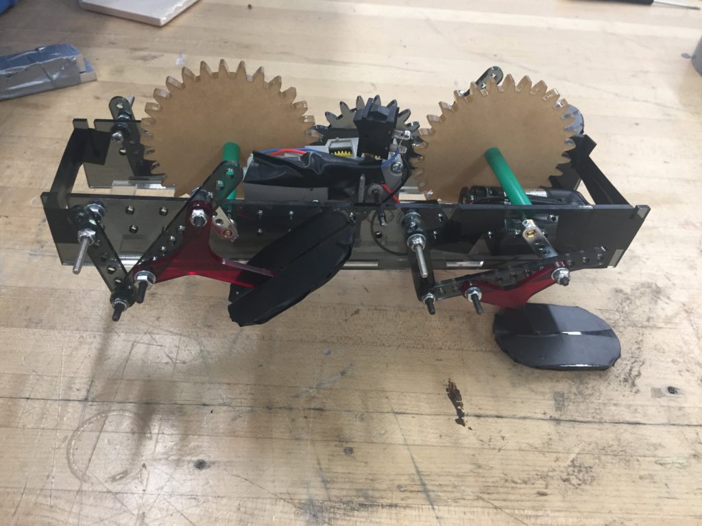
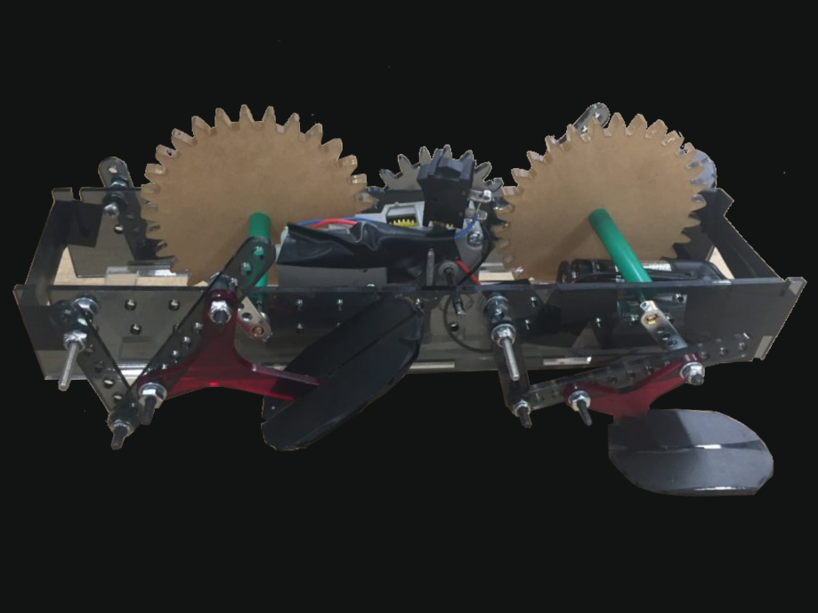
The aim of this project was to design a simple autonomous walking robot that would traverse 3 obstacles as fast as possible: stairs, stones, and hurdles. We were given coefficients for each obstacle, which represented the importance of that obstacle to our robots movement. Variable factors were linkage, feet, and gear ratios. The outer body, baseplate, and motor gearbox were fixed variables.
We based our coupler curve off the gait of a white-tailed deer, as they are nimble creatures that have to traverse many obstacles in their daily life. We noticed that their first movement from the ground is backward and upwards, which is useful for clearing obstacles in the stair and hurdle courses, our two highest coefficients. The curve then follows a horizontal ellipse, which makes sense for speed purposes since the foot touches down earlier and further forward than if the ellipse is angled upwards. To minimize this angle and keep the curve flat, we chose to place the foot centrally relative to the coupler. To summarize, our coupler curve is useful in avoiding obstacles without losing out on speed.
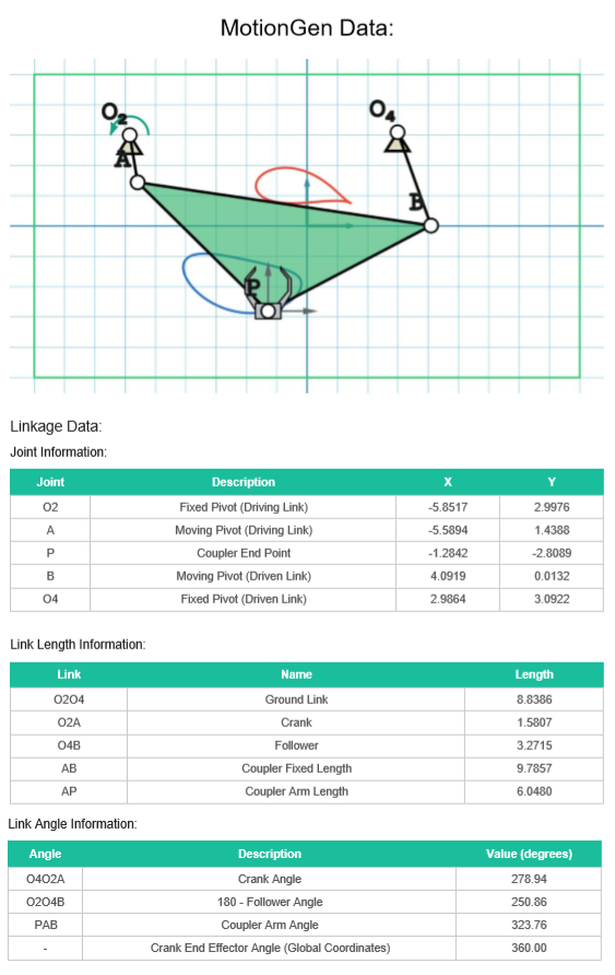
Link Lengths:
r1 = 2.00” (Frame)
r2 = 1.50” (Rocker)
r3 = 2.25” (Coupler)
r4 = .65” (Crank)
Note that this satisfies Grashof’s Law (r3 + r4 = 2.9” < r1 + r2 = 3.5”).
rp is the distance from the coupler/rocker junction to the foot. Beta is the angle between the coupler and this length. rp = 2.24” β = 41.2
Overall our final coupler curve is similar to our initial design, though there are some discrepancies. These arose from the holes we were attaching to having fixed lengths, limiting how much we could fine-tune our frame length. In addition, our crank length was also fixed as we chose to use the crank that came with the motor. By using these constrained lengths and using ratios from MotionGen to determine the remaining link lengths, we were able to produce a coupler curve that is fairly representative of our initial design.
Motor Characterization and Gear Ratio Selection
We measured the stall torque of the motor at 3V to be 0.29 oz-in. We did not use a gear ratio for this - we simply fixed the motor and used a notched lever arm and known weights to measure the stall torque.
Our measured stall torque of 0.29 oz-in is significantly lower than the manufacturer-specified stall torque of 0.5 oz-in, found in an online description of the motor. We expected the measured torque of the motor to be less than the advertised one; this could be due to a variety of factors including testing error.
For the gearbox we are using the configuration with the highest gear ratio, which is 203.7:1. We initially had the gearbox set to the mid-speed configuration (with a gear ratio of 58.2:1) but this did not provide sufficient torque for our robot and we switched to the higher ratio. The gear ratio for the additional stage outside of the gearbox was chosen to be 2:3. The total gear ratio is thus 305.55:1.
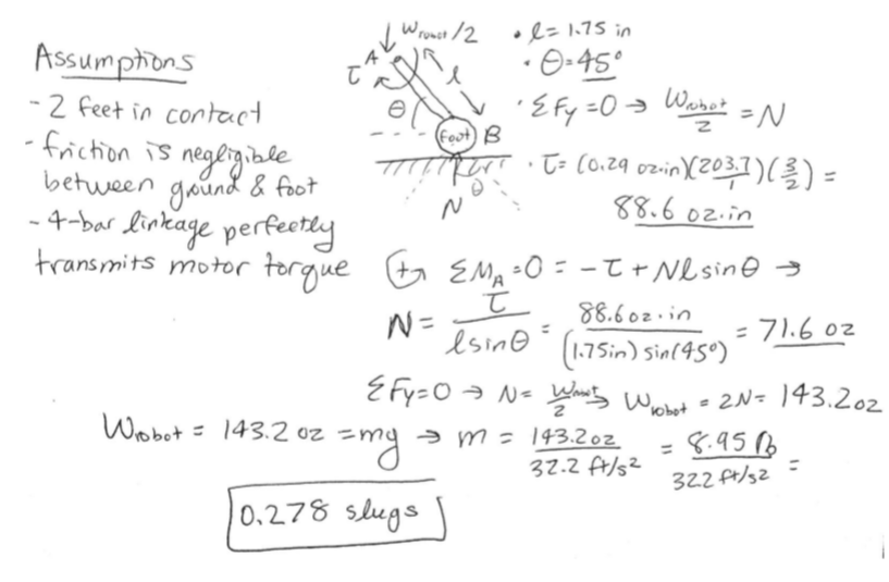
The maximum mass that our robot can support without stalling, given our measured motor torque and gear ratio, was estimated below to be 0.278 slugs = 4.06 kg. This seems very high, but is most likely artificially inflated due to our assumption that the 4-bar linkage perfectly transmits motor torque (in reality there is definitely a loss of torque here) and also our assumption that friction is negligible
Foot Design
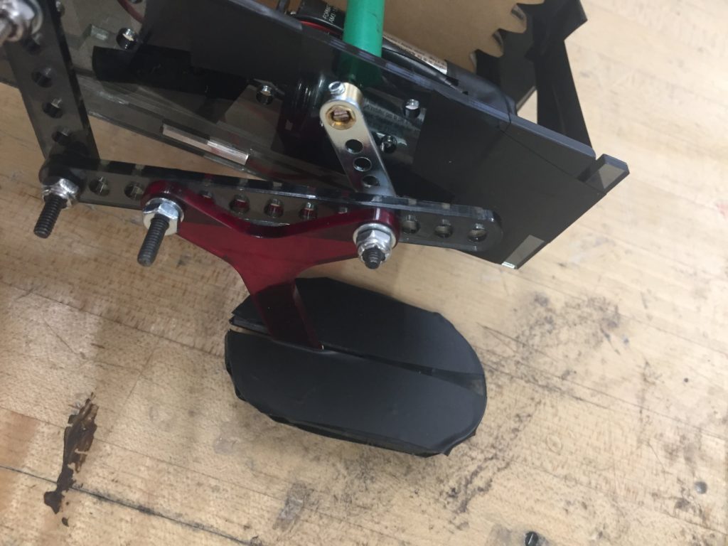
For our feet, we initially planned on using the yellow foam balls provided. These provided great stability but not enough friction, so we experimented with adding different friction coverings to the balls - high-friction silicone rubber, electrical tape, hot glue strips, etc. However, these still didn’t provide enough friction to make it up the stairs or over the hurdles. We decided to go with the flat design (acrylic covered with electrical tape and press-fitted onto the legs) to provide a greater surface area in contact with the ground. We tested it at several different angles with the leg and with several different tape coatings, on each of the three obstacle courses. We found that these feet work best when press-fitted all the way onto the legs (so that the foot sticks out in both the front and the back), perpendicular to the plane of the leg.
Our process for optimizing foot design was highly iterative with a trial-and-error component. We first iterated through different variants of the provided yellow foam balls with different friction coatings and positions on each obstacle. Once we abandoned the foam balls, we iterated through different positions, angles, and coatings on the flat acrylic feet before choosing the option that performed the best overall on all three obstacles.
Manufacturing a Better Mount Plate
We were also asked to design and prepare for manufacture a new baseplate design.
Design Requirements for Mount Plate:
1. The mount plate can be manufactured quickly (50,000 units in 9 months) and cheaply (so that the toy yields profit when sold at a reasonable market price, not yet determined).
2. Mating components can attach firmly and be positioned accurately. This requires slots and holes in the mount plate to have precise sizes and positions.
3. The mount plate is strong enough to be played with (e.g. dropped or kicked by a child) without yielding
4. The mount plate is stiff enough that deflections under typical loading don’t compromise the robot’s ability to walk
5. The mount plate is light enough to be played with by a child.
6. The mount plate’s geometry is suitable for the chosen manufacturing process.
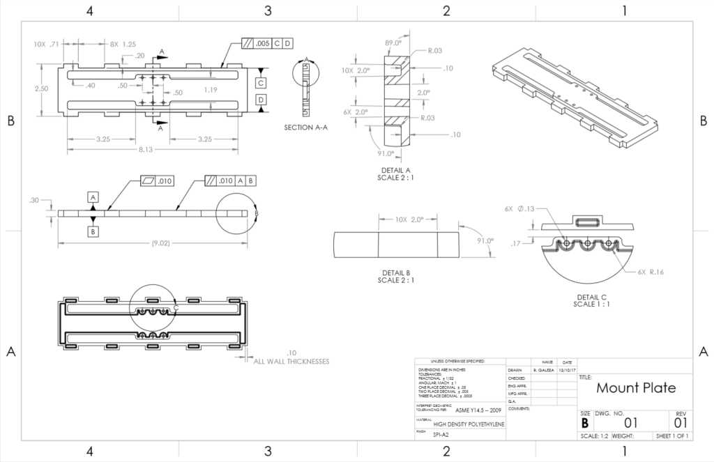
The mounting plate is a rectangular plastic platform for the walking robot’s components to mount to. It is stiffened with ribs on the bottom side. Slots are cut through the top face so that vertical plates (which make up the sides, front, and back of the robot body) can be press-fit into the mounting plate. Holes are cut through the top face so that the robot’s motor and gearbox can mount to the plate with screws and nuts. Our part is designed to be injection-molded: vertical faces are drafted and thicknesses are kept uniform. See the ‘Manufacturing Processes’ section below for the reasoning behind the decision to injection mold. The mount plate is made from HDPE plastic: see the ‘Material Choice’ section below for the reasoning behind that decision.
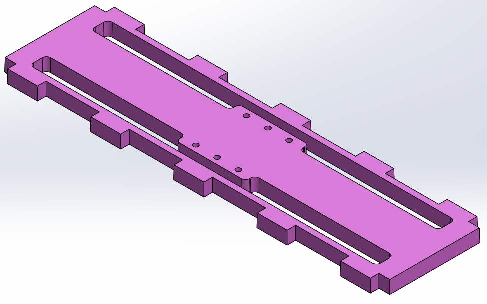
Rationale: ● The choice to injection mold fulfills the first and second design requirements: the process can produce our required volume quickly and economically, and it allows the part to have precise dimensions. See the ‘Manufacturing Processes’ section below for more detail on this choice. ● The slots and holes through the top face of the plate help to fulfill the second design requirement (mates with robot’s other components). ● The ribs on the mounting plate’s underside fulfill the third and fourth design requirements (adequate strength and stiffness). ● The choice of HDPE plastic fulfills the fifth design requirement (low weight). ● The part’s uniform thickness and draft on vertical faces fulfill the sixth design requirement (suitable geometry for the chosen manufacturing process).
Improvements over Kit Mount Plate: This injection-molded plate can be manufactured much more quickly and cheaply than the laser-cut acrylic kit plate. The achievable dimensional precision and ability to mate with other components are similar for the kit plate and our new design. The high-density polypropylene material has a lower yield strength (4,600 psi) than 1 acrylic (10,000 psi) , but our plate’s vertical ribs provide more strength and stiffness 2 than the flat design of the kit plate.
Manufacturing
Process: Injection Molding
We desired an inexpensive, rigid, relatively light, and relatively strong part, so we chose to make it from plastic. At a batch size of 50,000 units, compression molding and injection molding are the most economical plastic manufacturing processes. Our mount plate’s geometry is too complex to be compression-molded, so we chose to injection-mold it.
Material Choice: High Density Polyethylene (HDPE) Plastic
Our design requirements specify a material with light density, relatively high strength, and relatively high stiffness. These are properties of plastics. Of the plastics suitable for injection molding, HDPE is among the least expensive while having relatively high strength. This makes HDPE an excellent choice for our mount plate.
Cost Estimate
From the IPD Product Costing Guidelines, the fixed cost of injection molding (in U.S. dollars) can be estimated with:
Fixed Cost = (Base Cost) + (Mold Machining Cost)
Base Cost = 1000 + (10.58) (A) (d+6)^(.4)
Mold Machining Cost = (75) (A^.5) + (2700) [(.08) + (.04) (SP)]^(1.27) + 300 + (120) [A^(1.2) ]
A = area of mold base = (13 in.) (6.5 in) = 84.5 in^2
d = depth of mold = 0.3in
SP = number of surface patches = 16
Base Cost = $2,867.72
Mold Machining Cost = $27,395.30
Estimated Fixed Cost = $30,263.02
The variable cost can be estimated with:
Variable Cost = (Material Cost) + (Cost of Cooling Time)
Material Cost = (1.03) (C/W) (W)
Cost of Cooling Time = (2.18) (hmax)^2 / (alpha)
C/W = cost per weight of material = 0.90 $/kg
W = weight of part = 0.0406 kg (estimated in Solidworks)
hmax = maximum wall thickness = 0.10in
Alpha = thermal diffusivity of material = 0.11 mm^2 / s
Material Cost = $0.0376
Cost of Cooling Time = $0.1982
Estimated Variable Cost = $0.2358
Total Cost = (Fixed Cost) + (Num. Parts) (Variable Cost)
Estimated Total Cost = $42,053.02
Cost per part will be:
Cost Per Part = (Total Cost) / (Num. Parts)
Estimated Cost Per Part = $0.84
Documentation can be seen on the next page.